Wink of Knowledge: Gas Mixer
A night-time alarm and mysterious concentration peaks: we analyse a customer case in which leaky valves threatened the quality of the welding gas. Find out how continuous density measurement with the DGF-I1 exposed these ‘creeping quantities’ and how process monitoring can effectively prevent expensive rejects and plant downtime.
Why this test?
In welding technology (e.g. argon/hydrogen) and inerting processes (e.g. krypton/air), invisible factors often determine quality. If the mixing ratio is incorrect, welding defects or insulation losses may occur. We show how density serves as a ‘physical fingerprint’ to precisely monitor the concentration of binary gas mixtures – without costly laboratory analyses – and thus contributes to improved process stability.
What is a wink of knowledge?
Do you need to quickly measure, draw or do/build something? The speed with which the result may be achieved counts more than the perfect (scientific) approach. For this reason, we have introduced the Wink of Knowledge. Science in the wink of an eye, so to speak. We don’t want to prove anything scientifically. We simply want to quickly demonstrate something pragmatically. If you are interested, we would be happy to discuss these results in more detail with you and your project.
Which gases were used?
- Ar (Argon)
- H2 (Hydrogen)
Argon (Ar)
~1.78 kg/m³ at 0 °C, 1.01325 bar abs
Hydrogen (H2)
~0.09 kg/m³ at 0 °C, 1.01325 bar abs
Density measurement
The density was measured using the DGF-I1 gas density sensor. For this purpose, the existing calibration process was adapted and extended to include the measurement of pure SF6. The measured values recorded under varying pressure and temperature conditions were then used to optimize the existing physical model for concentration measurement. This model ensures that real gas calibrations with SF6 will no longer be necessary in the future, so that each sensor can be subsequently and easily configured for this application.
The TrueDyne sensor
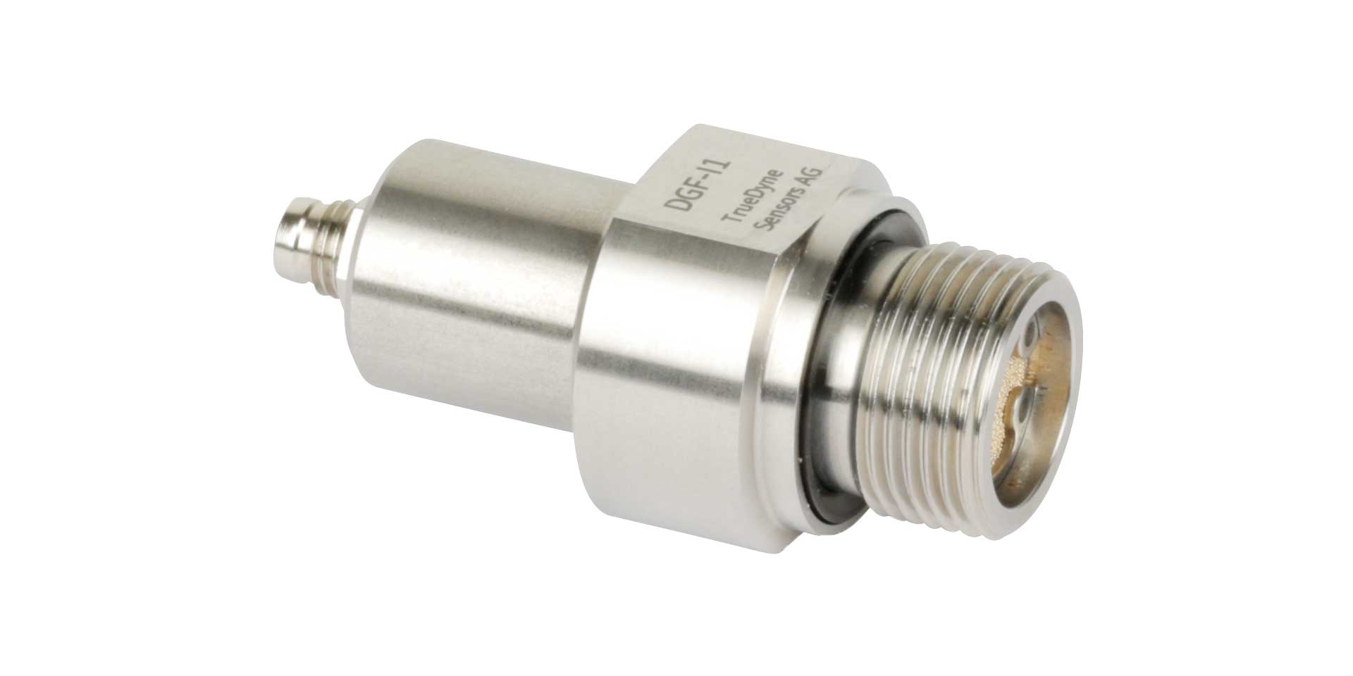
With a diameter of 33.5 mm and a length of 63 mm, the DGF-I1 density sensor has a very compact design and fits into even the smallest of spaces. It is screwed with the integrated connection directly into the gas line or the control cabinet to be insulated; a filter protects against contamination. The measured values are transmitted to the higher-level system via an RS485 interface. The low response time and power consumption of the sensor enable continuous monitoring of the desired SF6 concentration directly in the process – the measurement does not have to be interrupted.

DGF-I1 Density meter for gases
Max. measuring error:
Density: <0.1 kg/m³
Temperature: <0.8 °C
Pressure: <0.04 bar
In-field adjustment Density: <0.05 kg/m³
Repeatability:
Density: <0.015 kg/m³
Temperature: <0.06 °C
Pressure: <0.005 bar
Permissible density measuring range:
0,2 … 19 kg/m³
Permissible pressure range:
Max. Measuring range:
1…10 bar (absolute)
Only use gas mixtures with argon (Ar) up to
max 9 bar (abs).
Burst pressure 30 bar
Test setup
The test setup is used for the precise generation and continuous quality monitoring of binary gas mixtures. The system is supplied by two separate gas sources (gas cylinder A and gas cylinder B).
The dosing of the two individual gases is controlled by two mass flow controllers (MFC). These regulate the flow ratio precisely so that the desired target concentration is achieved. The two gas streams are then fed into a central buffer tank. This tank fulfils two functions: it serves to completely homogenise the gas mixture and compensates for pressure fluctuations and consumption peaks (buffering).
The measuring section is located at the outlet of the buffer tank. The finished gas mixture is fed directly through the DGF sensor. This monitors the concentration and quality of the mixture ‘inline’ immediately before it is fed to the downstream consumer (process). This ensures that only gas that meets the specifications enters the process.

Schematic setup of a gas mixing system with integrated DGF sensor monitoring
Results
 Figure 1: Concentration curve of the welding gas mixture
The graph above shows an example of the actual measurement log for hydrogen concentration in a welding gas mixing system over a period of three days (Tuesday to Thursday). The target value for the welding gas mixture was 5% H2. The orange boundary lines at 4% and 6% represent the maximum permitted tolerance of ±1% for the gas mixture.
At first glance, the periodic upward outliers that exceed the limit value of 6% are noticeable. It was precisely these peaks that triggered an alarm at the customer’s site at night, outside of regular production hours.
Diagnosis thanks to density measurement:
Analysis of the data recorded by the DGF-I1 quickly brought the problem to light:
- The phenomenon: The increase in H2 concentration correlated exactly with the downtime of the plant.
- The cause: An inspection of the gas mixing section revealed that the valve of the hydrogen mass flow controller (MFC) was no longer closing completely. So-called ‘creep volumes’ flowed continuously into the buffer tank.
- The effect: During ongoing production, gas consumption was high enough to mask these minor leaks – the mixture remained within the target range. However, as soon as consumption stopped, the light hydrogen accumulated in the tank and the concentration rose continuously and reproducibly above the permissible limit.
Conclusion
Added value for the customer:
Without continuous monitoring by the DGF-I1, this defect would have gone unnoticed until the scheduled maintenance of the MFCs, as the system appeared to be running correctly during regular operation. However, excessive hydrogen levels could have led to quality problems or porosity in the weld seams in the worst case.
Thanks to the clear data, it was possible to react immediately: until the defective MFC is replaced, gas can be briefly released from the buffer before production starts in order to restore the correct mixture value. This prevents production downtime until the defective MFC is replaced and ensures consistent welding quality.
Which sensor was used?
DGF-I1 density sensor for gases
- Click here to learn more about our sensor
Sensors that might interest you
Gases
Viscosity
Applications that might interest you


From volume (l)
to mass (kg)


More Winks of Knowledge that might interest you
Article: In-line measurements of the physical and thermodynamic properties of single and multicomponent liquids
Microfluidic devices are becoming increasingly important in various fields of pharmacy, flow chemistry and healthcare. In the embedded microchannel, the flow rates, the dynamic viscosity of the transported liquids and the fluid dynamic properties play an important role. Various functional auxiliary components of microfluidic devices such as flow restrictors, valves and flow meters need to be characterised with liquids used in several microfluidic applications.

Article: Density and Concentration Measurement Applications for Novel MEMS-based Micro Densitometer for Gas
Density and Concentration Measurement Applications for Novel MEMS-based Micro Densitometer for GasC. Huber, TrueDyne Sensors AG, Reinach BL (Switzerland), Endress+Hauser Flowtec, Reinach BL (Switzerland)Abstract A MEMS cantilever based resonant device for gas...

Article: Design, Simulation, Fabrication and Characterization of piezoelectric MEMS Cantilever for Gas Density and Viscosity Sensors Applications
Design, Simulation, Fabrication and Characterization of piezoelectric MEMS Cantilever for Gas Density and Viscosity Sensors ApplicationsA. Mehdaoui¹, C. Huber¹, J. Becker¹, F. Schraner¹, L. Villanueva² ¹TrueDyne Sensors AG, Reinach BL (Switzerland), ²Ecole...

Article: Multiparameter Gas-Monitoring System
The aim of the study is to develop a compact, robust and maintenance free gas concentration and humidity monitoring system for industrial use in the field of inert process gases. Our multiparameter gas-monitoring system prototype allows the simultaneous measurement of the fluid physical properties (density, viscosity) and water vapor content (at ppm level) under varying process conditions.

Part 3 – MEMS technology
MEMS technologyAt a glance In the previous section (part 2) we got to know the vibration measuring method. This section deals with the establishment of MEMS technology at TrueDyne Sensors AG. The technology has brought about the MEMS sensor, the heart of which is an...
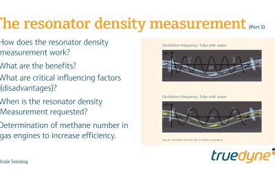
Part 2 – The resonator density measurement
The resonator density measurementAt a glance In the previous part (1) we learned about the basics of density measurement and the definition of density. This section is dedicated to the vibration method which is also used by density sensors for density measurement....
