 Proudly engineered in Switzerland
Flow sensor FLT-M1

The FLT-M1 flow sensor has been designed to determine the mass flow of liquids and gases. This is done with a mini Coriolis measuring system with an S-shaped measuring tube and a temperature sensor.
The flow sensor is installed directly in a flow pipe via a manufacturer-specific connection. If medium flows through the flow sensor, the measured value information is generated with the aid of Coriolis forces. The measured values are fed to the higher-level system via a Modbus TTL.
It is possible to take flow measurements for pressure lines up to 100 bar at a measuring rate of 200 Hz (200 measured values per second). Flow changes are recorded with a step response time of 50 ms.
Downloads
Contact
This product is designed for OEM applications in the field of plant and machine construction, where measuring instruments with high quantities and smallest variance are required. The device has no intrinsic safety, as the flow sensor is designed for integration into a device or system.
Dosing of delicate or expensive liquids
Measuring:
Dosing of delicate liquids consisting of several components. The flow components have been developed specifically for plant engineers. Highest precision with integrated electronics in combination with a very compact design.
Customer benefit:
- Quality improvement: High-precision monitoring/dosing of the components
- Optimizing the use of resources

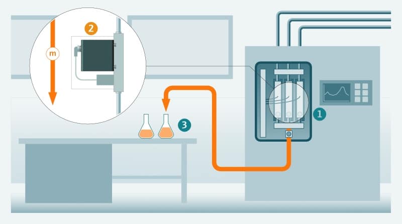
1. System for dosing and mixing of delicate and expensive liquid media. 2. Coriolis for monitoring the mass flow. In combination with a pump or a valve, a control circuit can be set up for optimal dosing. 3. Filling of media into suitable transport containers.
Specifications
General
- Mass flow
- Density
- Temperature
Units of measurement:
Adjustable
Performance
|
Max. measurement error: FLT-M1_i1
Repeatability: FLT-M1_i1
|
Max. measurement error: FLT-M1_i2
Repeatability: FLT-M1_i2
|
Temperature conditions
-10…+70 °C
Permissible ambient temperature:
-10…+80 °C
Permissible storage temperature:
-20…+85 °C
Range of application
|
Recommended flow measuring range: FLT-M1_i1 0…30 kg/h Pressure loss as a function of flow rate Permissible medium pressure: FLT-M1_i1 Max. 100 bar (rel.) Inlet and outlet sections: FLT-M1_i1 Inlet and outlet distances have no influence on the measuring accuracy. |
Recommended flow measuring range: FLT-M1_i2 0…120 kg/h Pressure loss as a function of flow rate Permissible medium pressure: FLT-M1_i2 Max. 100 bar (rel.) Inlet and outlet sections: FLT-M1_i2 Inlet and outlet distances have no influence on the measuring accuracy. |
Ambient conditions
Not specified
Electromagnetic compatibility:
Prepared for EMC 2014/30/EU (EN 61326-1)
Vibration and shock resistance:
Prepared for the following standards:
- IEC/EN 60068-2-6
- IEC/EN 60068-2-27
- IEC/EN 60068-2-31
- IEC/EN 60068-2-64
Degree of protection:
Housing is hermetically sealed, IP protection only when installed.
Dimensions
|
Dimensions: FLT-M1_i1 100 x 30 x 104 mm³ Weight: FLT-M1_i1 850 g Inner diameter of measuring tube: FLT-M1_i1 1.1 mm |
Dimensions: FLT-M1_i2 135 x 36,5 x 145 mm³ Weight: FLT-M1_i2 2150 g Inner diameter of measuring tube: FLT-M1_i2 2.5 mm |
Materials
Housing:
Stainless steel, 1.4301 (304L)
Wetted parts:
Stainless steel, 1.4404/1.4435 (316L)
Option wetted parts for FLT-M1_i1:
Alloy C22, 2.4602
Fluidic interfaces
Manufacturer-specific connection.
Electrical interfaces
Connection:
Solder pins with 1 mm diameter, 7-pole
Communication:
- Modbus TTL
Power supply:
DC 10…35 V (max. 1 Watt). No galvanic isolation
Connection pin assignment:
| Pin | Assignment | Modbus TTL |
| 1 | V+ | Supply voltage |
| 2 | SDA | Modbus Tx |
| 3 | SCL | Modbus Rx |
| 4 | NC | Modbus T/R |
| 5 | CDI-Rx | Serial transmission (service interface) |
| 6 | CDI-Tx | Serial reception (service interface) |
| 7 | GND | Reference potential for all circuits |
Certificates and approvals
The flow sensor is intended to act as an electronic component for integration into a device or system. The flow sensor is not a stand-alone measuring device and therefore does not require the CE mark to be affixed.
RoHS:
All installed components meet the requirements of the RoHS Directive.
Zero point adjustment
- When highest accuracy is needed at low flow rates.
- When process conditions are extreme, e.g. very high process temperature.
For a zeropoint adjust the following pre-conditions need to be fulfilled:
- Measuring line is completely shut off, i.e. real flow is truly zero!
- Measuring tube is filled homogeneously and pressurized with at least 15 psi (gauge) to avoid gas bubbles in the fluid, when measuring gas no condensation is allowed.
During the zeropoint adjust stability of measured flow rate is monitored and its mean value is built for new zeropoint value. This typ. takes 20 s. If the process conditions are not suitable zeropoint adjust is aborted and old zeropoint value remains valid
Flow damping
Low Flow Cutoff
So it’s ensured that totalizer is stopped properly and cannot creep away.
Low flow cutoff is left when mass flow overruns 150% of set threshold (hysteresis).
When low flow cutoff is active no status message is set.
