 Proudly engineered in Switzerland
Viscosity sensor VLO-M2_ex for liquids

![]() The VLO-M2_ex sensor for use in hazardous areas according to ATEX: II1G and IECEx: Zone 0 measures the density and viscosity of liquids in a microelectromechanical system (MEMS system). Within the MEMS system, the liquid is directed to an omega-shaped microchannel, the so-called omega chip. This tiny silicon tube – it is hardly thicker than a hair – is set into oscillation for the measurement. The density of the medium can be derived from the natural frequency of this oscillation: the denser the medium, the lower the oscillation.
The VLO-M2_ex sensor for use in hazardous areas according to ATEX: II1G and IECEx: Zone 0 measures the density and viscosity of liquids in a microelectromechanical system (MEMS system). Within the MEMS system, the liquid is directed to an omega-shaped microchannel, the so-called omega chip. This tiny silicon tube – it is hardly thicker than a hair – is set into oscillation for the measurement. The density of the medium can be derived from the natural frequency of this oscillation: the denser the medium, the lower the oscillation.
Thanks to measurement in the MEMS system, the sensor is only 37 x 83 x 18.2 mm³ in size and can be accommodated even in tight spaces. The high-precision measurement results are immediately available, allowing continuous measurement during the process. The density of liquids depends on their temperature. To compensate for this effect, an integrated platinum resistor detects the temperature of the liquid.
The density sensor sends the measured data to the readout system via the data line in Modbus RTU transmission mode.
Downloads
Contact
Product description
Modbus RTU
- Modbus RTU
- RS-485 Point to point connection
- Modbus over serial line – Specification
Inline measurement
- Right in the running process
- Values are output instantaneously
- Quick change of media possible
Density
- Density value
- Max. measurement deviation:
±0.2 kg/m³ (or 0.0075 x abs (T-25 °C)] kg/m³ if the value is >0.2 kg/m³) - Repeatability: ±0,1 kg/m³
Viscosity
- Viscosity value: Dynamic & kinematic
- Max. Measurement error:
±[0.2 mPa s + 5% of measured value] - Repeatability: ±0,1 mPa s
Fluids
- Hydrocarbons
- Aqueous media
- and much more – ask us
Concentration packages (option)
- Sugar/ water according to ICUMSA (%mass)
- NaCl / water accordring to Laliberté / Cooper (%mass)
Continuation Concentration Packages
- High fructose corn syrup HFCS42, HFCS55, HFCS90 (%mass / °Brix / °Plato / °Balling)
Continuation Concentration Packages
- Ethanol / water according OIML IST-90
(%mass / %vol@20°C / ABF@20°C)
Continuation Concentration Packages
- Methanol / water (%mass)
- Ethylenglycol / water (%mass)
Continuation Concentration Packages
- Mineral content in water according to Huber (mg/l)
- Hydrogen peroxide in water (H2O2) (%mass)
Applications
Airfield Refuelling
When kerosene is pumped from the airfield distribution system into an aircraft by a pump truck, the volume of fuel is recorded as standard. However, since the density varies according to pressure and temperature, it is not possible to make precise statements about the mass. For this reason, samples are taken from the tank farm throughout the day and handed over to the pilot for calculation of the mass. With the VLO-M2_ex sensor from TrueDyne, you can collect the necessary data on the density during the process and use them to calculate the mass (V-ρ=m).
Together with the volumetric measurement, the density can be used to calculate the mass of the fuel in kilograms, which is then handed over to the customer. In addition, the density provides important information about the quality of the fuel, which is another safety feature in flight operations.

1. Standardised volumetric measurement in litres. 2. Installed in a bypass line, the viscosity sensor VLO-M2_ex measures the density directly on the pump truck. Thanks to the compact design of the sensor, it can also be retrofitted into the process. 3. The kerosene is pumped from the airfield distribution system into the aircraft.
Engineering
Overview
The density sensor was designed for measuring the density of fluids. This takes place using a microelectromechanical system (MEMS) with a microchannel shaped liked the Greek letter omega (omega chip), which is built into an internal bypass.
When the medium flows through the density sensor, the bypass arrangement generates a pressure gradient via the microchannel, which allows the medium to reach the omega chip. The medium influences the physical properties of the excited sensor (resonance frequency and quality), and these are digitized and evaluated in the microcontroller. The measured values can be read out via the serial interface (RS-485, Modbus).
Density measurements in the range 600 to 1000 kg/m3 (further options see product specifications) can be realized at a flow rate of 0 to 10 l/h.
Omega chip
The omega chip, a vibronic microsystem, is the heart of the measuring system and is used for sensor signal generation in the overall system. An essential component of this microsystem is a silicon tube (microchannel), which is electrostatically set into oscillation in a vacuum atmosphere. To compensate for temperature effects, a platinum resistor is integrated, which allows local real-time temperature measurement. The omega chip essentially consists of crystalline silicon and glass.
")
Measuring principle (omega chip)
Density measurement
The density sensor uses the omega chip for density measurement. For this purpose, the filled microchannel is brought to resonant oscillation and analyzed.
The resulting natural frequency of the microchannel depends on the mass and thus on the density of the medium in the microchannel: The greater the density of the medium, the lower the natural frequency. Thus the natural frequency is a function of the medium density.

f = natural frequency, E ⋅ I = stiffness of the tube, ρTube = tube density, ATube = tube cross-section, ρFluid = medium density, AFluid = medium cross-section
Specifications
General
Indicators:
Density and variables derived from it (e.g. standard density, concentration, etc.)
Typical media:
Particulate free (<30 μm) media such as
- Gasoline, diesel, kerosene
- OME (synthetic materials)
- Oils and lubricants
- Water-based media
- Methanol, ethanol, isopropanol
- LPG*
- AdBlue®*
- Glycol mixtures*
Other media can be used after individual clarification. *Optional
Concentration packages:
- Various sugars in water
- Invert sugar in water
- High fructose corn syrup
- Methanol in water
- Ethanol in water
- Salt in water
- Minerals in water
- Hydrogen peroxide in water
- Ethylene glycol in water
- Butane in propane
Note: User-specific concentration packages on request
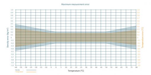
Measurement performance
Max. measurement deviation:
Viscosity: ±[0,2 mPa s + 5% of reading]
Density: ±0.2 kg/m³ (or 0.0075 x abs (T-25 °C)] kg/m³ if the value is >0.2 kg/m³)
Temperature: ±0.15 °C (or ±[0.005 x abs(T-25 °C)] °C if the value is >0.15 °C)
Repeatability:
Viscosity: ±0,1 mPa s
Density: ±0,1 kg/m³
Temperature: ±0,05 °C
Temperature conditions
Permissible medium temperature:
-40 …..+60 °C
Permissible ambient temperature:
-40 …..+60 °C
Permissible storage temperature:
-40 …..+60 °C
Specifications
Permissible density measuring range:
0…1600 kg/m³
Permissible viscosity range:
0,3…50 mPa s
Permissible pressure of medium:
0…20 bar (abs)
Burst pressure: 80 bar (abs)
Permissible particle size:
Max. 30 μm
Permissible flow rate range:
0…10 l/h (water)
Vibrations:
Vibrations (<20 kHz) have no influence on the measuring accuracy due to the high working frequency of the microchannel.
Inlet and outlet sections:
Inlet and outlet sections have no influence on the measuring accuracy.
Ambient conditions
Climate class:
Not yet defined
Electromagnetic compatibility:
EMC 2014/30/EU (EN 61326-1)
Vibration and shock resistance:
Not yet defined
Degree of protection
IP54 (IEC 60529)
Material
Housing:
Stainless steel:
- 1.4404 (316L)
- 1.4542 (AISI/SUS 630)
In contact with media:
Stainless steel:
- 1.4542 (AISI/SUS 630)
BOROFLOAT® 33 glass
Silicon
Epoxy resin
Dimensions / Design
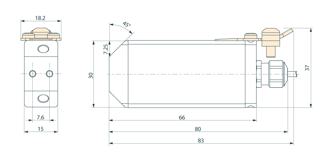
Design: VLO-M2_ex
Dimensions:
30 mm x 66 mm x 15 mm (without cable, cable gland and connection for protective ground)
Weight:
<200 g
Dimensions of measuring channel:
160 x 200 μm (500 nl)
Fluidic interfaces
Fluidic interfaces:
2 x M5 threaded holes at a 45° angle to the side and front surfaces
Electrical interface
Communication:
Continuous, without the need for an external command.
On the hardware standard RS485.
Proprietary Modbus RTU communication protocol (see data sheet)
Cable design:
Permanently installed cable. Connection cable type KS-Li9YD11Y 4xAWG 28, manufacturer: Kabel Sterner
Cable length:
3 m (option up to 30 m)
Cable external diameter:
2.3 mm
Wire diameter:
4 x AWG 28
Level control:
Digital communication lines and power supply in one common shielded cable, unidirectional, RS-485
Provide termination resistance of 330 Ω on the client side
Energy supply:
Maximum current consumption 26 mA, maximum power consumption 350 mW
Supply: 9.4 V…13.3 V (type: 12 V)
For DLO-M2_ex XA observe safety instructions – Zener barriers (supply and RS485)
Dielectric strength
The reference potential (GND) is connected to the housing and the earth connection (see product structure). There is no electrical isolation between the supply circuits, the communication interface and GND
Data rate:
Response time 100 ms
Cable assignment:
Wire colour assignment
yellow – RS485 B, D1
green – RS485 A, D0
brown – GND (signal ground), common
white – VDD (supply voltage)
blank – shielding
Certificates / Approvals
CE mark:
The density sensor meets the legal requirements of the EC directives. TrueDyne Sensors AG confirms successful testing of the density sensor with attachment of the CE mark.
Directives:
- ATEX 2014/34/EU (L96/309)
- LVD 2014/35/EU (L96/357)
- EMC 2014/30/EU (L96/79)
- RoHS 2011/65/EU (L174/88)
Standards:
- EN 61010-1:2010
- EN IEC 60079-0:2019
- EN 60079-11:2012
- EN 61326-1:2013
- EN 61326-2-3:2013
- EN 50581: 2012
Product structure

Product structure: VLO-M2_ex
- Density sensor DML02(_ex)
- Mounting holes for mechanical fastening (6 x M3 threaded holes)
- Fluidic interface (2 x M5 threaded holes)
- Clamp on earthing plate with screws M3×8 TORX
- Electronic interface for communication and power supply

Mechanical fastening: VLO-M2_ex